Playing With Amateur Radio

Category: Fixing

TS-940S Repair

A few years ago, I picked up a Kenwood TS-940 for a song: just twenty quid.

Of course, the reason it was so cheap, is that it didn’t work.   Completely dead, it was.

I checked the fuse – it had blown. So I replaced it and that blew too.  A bit of fault-finding soon revealed the bridge rectifier bolted to the back of the heatsink was the culprit. I typed it’s part number into ebay and it found just one for sale. In the states. For 93 dollars! Plus shipping. Sod that.  I found a higher spec’d one at Farnells for six quid, fitted it and was pleased to see the radio spring into life.

Well, limp into life.

The frequency display only showed for a few seconds and then disappeared, showing just a row of dots. Also, there was no receive audio; no transmit, no sub-display and some of the panel buttons didn’t seem to do anything.

Other than that, it worked perfectly!

Some research on the internets showed that this old 1990’s radio was prone to a number of issues, the most problematic being the poorly designed PSU.  I made a few changes to the AVR board – as suggested on several websites – and checked all the voltages therein as per the Kenwood Service Manual.  Everything was in spec –  or near enough, anyway – but the faults persisted.  I didn’t have time to look at it any further, so it got tucked away in the corner of the shack where it gathered lots of dust, until last week when I dragged it onto the bench for another look.

Further research revealed that if any of the 940’s 6 PLL circuits was unlocked, this could be the cause of the display dots problem.   With the help of a brilliant document dedicated to this issue, written by Dave KB7JS, I managed to figure out which of the PLLs on my 940 was unlocked. Figuring out why it was unlocked, wasn’t so easy though. Voltages around the transistor were nowhere near what they should have been, with zero volts on the base and bugger all on the emitter.
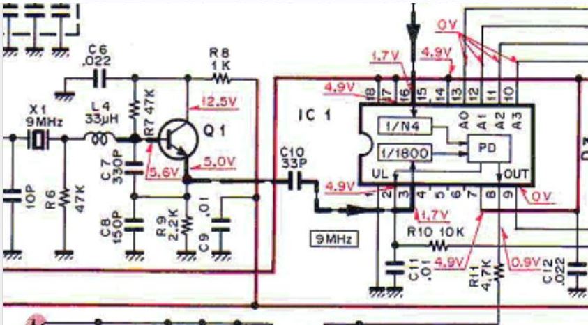
I removed Q1 and X1 and tested them. They seemed fine. I removed resistors R6, R7, R8 and R9. They also tested fine. I followed that up with C6, C7, C8, C9 and C10. All tested OK. I even removed and tested L4, as unlikely as it was that it might have failed. It hadn’t.

A friend suggested that maybe something was failing under load, so I rebuilt the circuit with new components – Q1 being no longer available, I stuck a BC547 in… a different pinout, but it fitted… eventually.

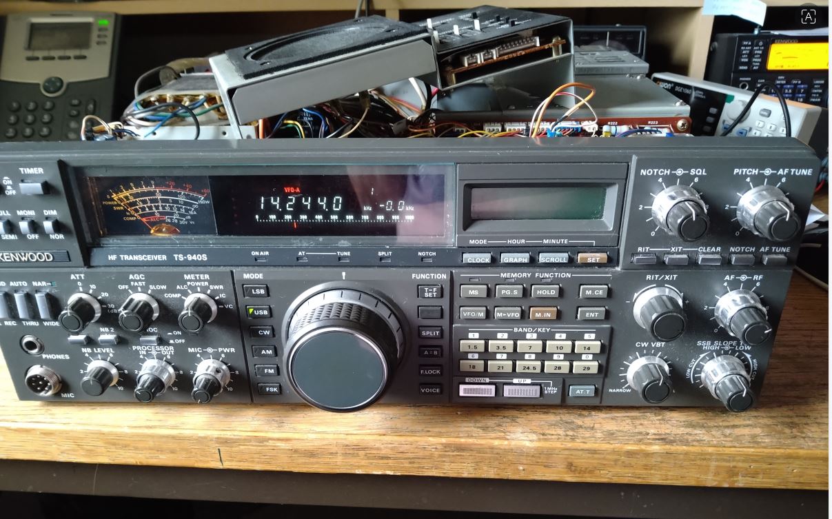
I was rewarded with all six PLL’s locking and the display acting as it should, as per the picture above.  On top of that, I now had some receive audio! Hurrah!

The radio seems a bit deaf… which is unusual, because owners of these rigs often boast about how good the RX side of things is, so that’s one of the next problems I’m going to have to look at.

Whether I’ll be able to fix all the issues this rig has, I don’t know.

But it’ll be fun finding out.


Kenwood TM-V71A motorboating

I’ve been getting some complaints recently, about the audio from my Kenwood TM-V71A that I use in the car.

It has developed a ‘motorboating’ sound that sits at the back of my audio.

Strangely, it seems far more prevalent when I’m going through a repeater. No idea how that could be.

I had this problem a couple of years ago and a search on the internets showed that I wasn’t alone. Lots of people had the same issue with this rig. Research had shown that the culprit was the clock signal travelling between the microphone and the rig itself. That clock signal is needed for the keys on the mic to work.

A potential fix was to try re-crimping the RJ45 plugs on the mic cable. I tried this and sure enough, it worked.

But now the problem was back and I wanted a more permanent solution,

As I never use the keypad on the mic, the obvious solution was to just cut that clock pin. I have had the radio for about 8 years and have never used the keypad, but I know that as soon as I permanently disable it, I’ll need to use it for something.

And, so I decided a switch would be best, so I can disconnect or reconnect the clock wire as and when required.

Searching through my box of switches, I happened across a small tilt switch. I thought this would be a good idea, as the mic is in a vertical position when talking, but horizontal when keying something in. I drilled a small hole in the PCB to take the switch and wired it in: There are two circuit boards in the mic, with some wires going between them. The black wire is the clock wire, so I just cut that and lengthened it to reach the switch.

Turns out, it was a rubbish idea! The switch would activate at 45 degrees (of course!). Luckily, I had a very small slide switch, which fitted between the two boards quite easily. A small hole cut in the side of the mic casing and a dab of Superglue had it looking almost like it had been factory fitted. Almost.

Nonetheless, it does the job perfectly and my audio reports are “excellent” once more.

Adapting

Back in 2013, I fitted a new Diamond X-50 colinear on the side of the house.  A 12 metre length of  UR67 coax connected it to the radio.

Now, the X-50 came fitted with an N-Type socket and when I mentioned at the local emporium that I’d never made up an N-Type before, I was advised that they were a bit fiddly and it would be easier to use an N-Type to SO239 adaptor.

So I did.

It all worked really well and was certainly an improvement over the Slim Jim I’d had years before.

But over the years, I noticed a drop in performance. GB3HR, which I had been able to get into with little problem,  slowly slipped into the noise and eventually became unreadable with me.  At first, I thought this was due to the repeater owners reducing selectivity, to try and prevent the troll that sits on there from getting access.  But then I noticed other issues.

Eventually (two weeks ago), I decided to replace the X-50 with an X-200, giving slightly more gain, and also replace the UR67 with some Ultraflex10 – again providing slightly less loss.

The difference has been tremendous! So much better than I had estimated with the 2dB gain I’d calculated.

So, I looked at the X-50,  to see if I could see any reason why it had been under-performing and I noticed that the aforementioned adaptor was at fault.  Whilst it looked clean and to be in good nick, the petals on the SO239 part must have shrunk slightly, as when I undid the PL259 connector from it, the weight of just one metre of RU67 cable was enough for the plug to slip out of the adaptor. It looked perfect, but was really loose fitting.  I have tried other PL259 plugs and they all fall out, just the same.

So, I’m guessing the adaptor was the cause of this underperformance, all along.

The new aerial doesn’t have an adaptor, as I fitted an N-Type directly to the cable: yes, it’s a bit fiddly, but really not that difficult, it turns out.

And now I know how to do them, I’ll be fitting them on all my VHF/UHF cables.

And I’ll definitely not be using any adaptors again!

Dead Handy

My Wouxon KG-UV8D stopped working the other day.

Two thoughts crossed my mind simultaneously:

“Oh bugger, I suppose I’ll have to spend out on a new handheld now”.

“Yay!  I can go shopping for a new handheld now”.

Still, being the curious radio amateur that I am, I decided to see if it was fixable.

A quick investigation showed the battery had run out of charge, despite it sitting in the charger for the previous 24 hours.  Hmmm.  I checked the charger, and sure enough, there was no voltage on the terminals.

I was somewhat dismayed when I opened up the charger and could see nothing immediately obvious.  Also, it was nearly all SMD… all too small and fiddly for my liking – I like proper components that you can actually pick up with your fingers.

Also also, I couldn’t find a schematic for it.

But, I started tracing voltages through anyway and it wasn’t long before I found a component with volts and one side and nada on the other.  Either a diode or a blown resistor, maybe.   It had no values shown on it, just the letter H.  A bit of research on the internets and some conversations with some fellow hams suggested it was most likely a 1A fuse. Bridging it with a piece of wire proved that to be the most likely case as the charger started working properly.

I didn’t want to leave the fuse bridged out – fuses are there for a reason after all – but a replacement SMD fuse on ebay was about four quid.  Yes, four quid! For a fuse!

So, I used a 20mm cartridge fuse of the right value, slipped some heatshrink over it and wired that in instead.

Put it all back together and it works a treat. No need to buy a new one.

Whilst trying to find a schematic on the internet, I read of many instances where this charger has failed, so I thought I’d write it up here for anyone who might have a similar issue.

© 2026 Station G6WRB

Theme by Anders Norén — Up ↑

By law, I need to tell you that this sites collects cookies, containing info about your IP address and shit like that.
Don't worry, I don't do anything with that information... I have far more interesting things to do.
Oh, if you must... I accept.