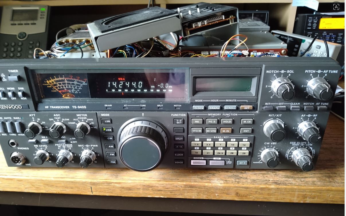
 A few years ago, I picked up a Kenwood TS-940 for a song: just twenty quid.
Of course, the reason it was so cheap, is that it didn’t work. Completely dead, it was.
I checked the fuse – it had blown. So I replaced it and that blew too. A bit of fault-finding soon revealed the bridge rectifier bolted to the back of the heatsink was the culprit. I typed it’s part number into ebay and it found just one for sale. In the states. For 93 dollars! Plus shipping. Sod that. I found a higher spec’d one at Farnells for six quid, fitted it and was pleased to see the radio spring into life.
Well, limp into life.
The frequency display only showed for a few seconds and then disappeared, showing just a row of dots. Also, there was no receive audio; no transmit, no sub-display and some of the panel buttons didn’t seem to do anything.
Other than that, it worked perfectly!
Some research on the internets showed that this old 1990’s radio was prone to a number of issues, the most problematic being the poorly designed PSU. I made a few changes to the AVR board – as suggested on several websites – and checked all the voltages therein as per the Kenwood Service Manual. Everything was in spec – or near enough, anyway – but the faults persisted. I didn’t have time to look at it any further, so it got tucked away in the corner of the shack where it gathered lots of dust, until last week when I dragged it onto the bench for another look.
Further research revealed that if any of the 940’s 6 PLL circuits was unlocked, this could be the cause of the display dots problem. With the help of a brilliant document dedicated to this issue, written by Dave KB7JS, I managed to figure out which of the PLLs on my 940 was unlocked. Figuring out why it was unlocked, wasn’t so easy though. Voltages around the transistor were nowhere near what they should have been, with zero volts on the base and bugger all on the emitter.
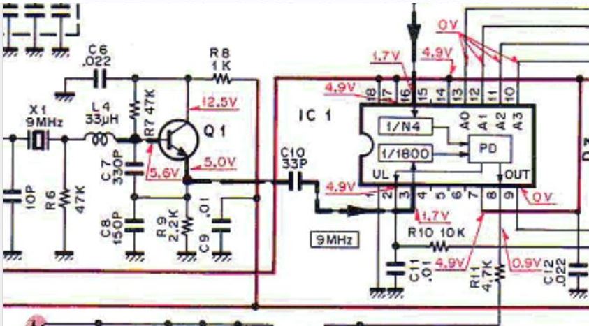 I removed Q1 and X1 and tested them. They seemed fine. I removed resistors R6, R7, R8 and R9. They also tested fine. I followed that up with C6, C7, C8, C9 and C10. All tested OK. I even removed and tested L4, as unlikely as it was that it might have failed. It hadn’t.
A friend suggested that maybe something was failing under load, so I rebuilt the circuit with new components – Q1 being no longer available, I stuck a BC547 in… a different pinout, but it fitted… eventually.
I was rewarded with all six PLL’s locking and the display acting as it should, as per the picture above. On top of that, I now had some receive audio! Hurrah!
The radio seems a bit deaf… which is unusual, because owners of these rigs often boast about how good the RX side of things is, so that’s one of the next problems I’m going to have to look at.
Whether I’ll be able to fix all the issues this rig has, I don’t know.
But it’ll be fun finding out.
Leave a Reply